- Power Cables
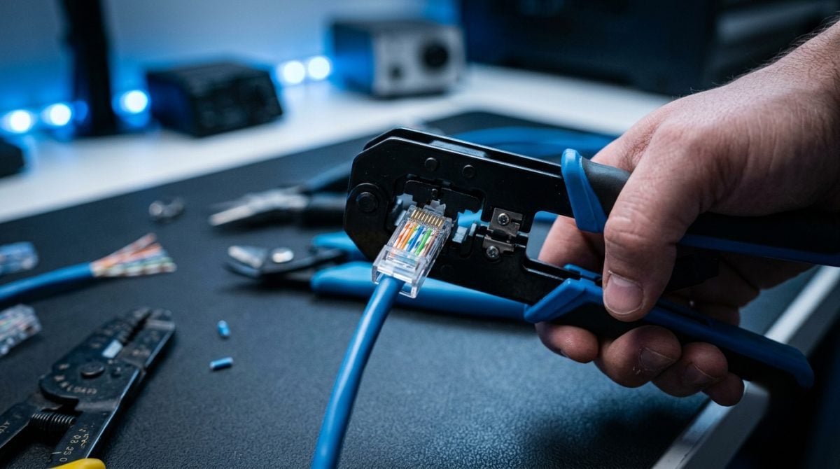
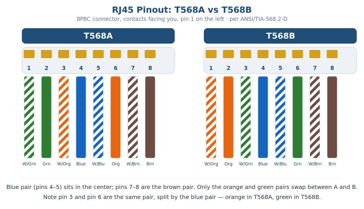
- Network Cables
- Fiber Optic Cables
- USB Cables
- HDMI Cables
- DisplayPort Cables
- Audio Cables
- Phone Cables
- Serial Cables
- Apple Lightning Cable
- DVI Cables
- Video Cables
- Mini DisplayPort Cables
- Computer Cables
- Monitor Cables
- Bulk Wire & Cable
- Security Camera Cables
- Cable Management
- Shop All Power Cables
- Hospital Grade Power Cord
- Universal Power Cords
- Power Cord Extension
- International Power Cords
- Laptop / Notebook Power Cords
- DC Power Cables
- Shop All Network Cables
- Cat5e Patch Cables
- Cat6 Patch Cables
- Cat6a Patch Cables
- Bulk Network Cables
- RJ45 Dust Cover
- RG58 BNC Thinnet Coaxial Cables
- Shop All Fiber Optic Cables
- Multimode 62.5/125 OM1
- Multimode 50/125 OM2
- Multimode 50/125 OM3
- Multimode 50/125 OM4
- Multimode 50/125 OM5
- Singlemode 9/125 OS2
- Shop All USB Cables
- USB 3.0 Cables
- USB 2.0 / 3.0 Repeaters
- USB 2.0 Cables
- USB Converters
- USB 3.1 Type C Cables
- USB 4.0 Type C Cables
- USB Dust Cover
- Shop All HDMI Cables
- HDMI with Ethernet
- HDMI to Micro HDMI
- HDMI to Mini HDMI
- HDMI to DVI
- HDMI Amplifier Splitter
- Active Fiber HDMI Cables
- Active HDMI Cables
- Ultra High Speed HDMI 2.1
- HDMI Dust Cover
- HDMI Extender
- Shop All DisplayPort Cables
- DisplayPort To HDMI
- DisplayPort to DisplayPort
- DisplayPort To DVI
- DisplayPort To VGA
- Shop All Audio Cables
- 3.5mm Audio Cables
- RCA Audio Cables
- Optical Toslink Cables
- XLR Microphone Cables
- Shop All Phone Cables
- RJ11 6P4C Silver Satin
- RJ12 6P6C Silver Satin
- RJ45 8P8C Silver Satin
- Bulk Phone Cables
- Shop All Serial Cables
- RS-232 Serial Cables
- RS-449 DB37 Serial Cables
- AT Serial Printer Cables
- Serial Adapter Cables
- AT Serial Modem Cables
- Null Modem Cables
- Shop All DVI Cables
- DVI Digital Cables
- DVI Integrated Cables
- DVI to VGA Cables
- DVI Analog Cables
- DVI Dust Cover
- DVI to HDMI Cables
- Shop All Mini DisplayPort Cables
- Mini DisplayPort to DVI
- Mini DisplayPort to DisplayPort
- Mini DisplayPort to HDMI
- Mini DisplayPort to VGA
- Mini DisplayPort to Mini DisplayPort
- Shop All Computer Cables
- SCSI Cables
- Mini SAS Cables
- SFP+ Cables
- Parallel Printer Cables
- IEEE 488 GPIB/HPIB Cables
- Internal Molex Cables
- IEEE 1394 Firewire
- ATX Power Cables
- Mouse and Keyboard Cables
- KVM Cables
- SATA/eSATA/SAS Cables
- MIDI & CD ROM Audio Cables
- Apple Computer Cables
- D-Sub Jumper Wire
- Cisco Cables
- Shop All Monitor Cables
- VGA Cables
- SVGA Cables
- VGA to BNC Cables
- VGA to RCA Cables
- VGA Splitter Cables
- Shop All Security Camera Cables
- CCTV Power Adapters
- DC Power Pigtail
- BNC + DC Combo Cable
- BNC + RCA + DC Cable
- Universal AC Power Cords
- Extension Power Cords
- Data Center Power Cords
- Notebook Power Cords
- Monitor Power Adapter Cords
- Outdoor Power Cords
- Hospital-Grade Power Cords
- NEMA 1-15P Power Cord
- NEMA 5-15P Power Cord
- NEMA 5-20P & 6-20P Power Cord
- NEMA 6-15P Power Cord
- NEMA Locking Power Cord
- IEC C14 Power Cord
- IEC C20 Power Cord
- International Power Cords
- Surge Protector and Power Strips
- Shop All Extension Power Cords
- C14 to C13
- C14 to C13 & C5
- C20 to C19
- 5-15P to 5-15R
- L5-15P to L5-15R
- Shop All Data Center Power Cords
- L5-15P to L5-15R
- C14 to C15
- C14 to C19
- C20 to C13
- C20 to C19
- 5-15P to C15
- 5-15P to C19
- L6-20P to C19
- C20 to C15
- C20 to C21
- L5-20P to C19
- 6-15P to C13
- 6-20P to C13
- L5-30P to L5-30R
- 6-20P to C19
- L6-20P to C13
- L6-20P to C15
- L5-20P to C13
- L6-30P to C13
- L6-30P to C19
- L6-30P to L6-30R
- L5-15P to C13
- Shop All Notebook Power Cords
- 5-15P to C5 (3-Prong)
- 1-15P to C7 (2-Prong Non-Polarized)
- 1-15P to C7 (2-Prong Polarized)
- C14 to C13 & C5 (3-Prong)
- Shop All NEMA 1-15P Power Cord
- 1-15P to C7 (Non-Polarized)
- 1-15P to C7 (Polarized)
- Low Profile 1-15P to C7 (Non-Polarized)
- Low Profile 1-15P to Right-Angled C7 (Non-Polarized)
- Shop All NEMA 5-15P Power Cord
- 5-15P to C5
- 5-15P to C13
- 5-15P to C13 x2
- 5-15P to C13 Right Angled
- 5-15P to C15
- 5-15P to C19
- 5-15P to 5-15R
- Low Profile Angled 5-15P to 5-15R
- 5-15P to 5-15R x 2
- Low Profile Angled 5-15P to 5-15R x 2
- 5-15P to NEMA 5-15R x 3
- 5-15P to ROJ
- Shop All NEMA 5-20P & 6-20P Power Cord
- 5-20P to C13
- 5-20P to C19
- 5-20P to 5-20R
- 6-20P to C13
- 6-20P to C19
- Shop All NEMA Locking Power Cord
- NEMA L5-15P to C13
- NEMA L5-15P to L5-15R
- NEMA L5-20P to C13
- NEMA L5-20P to C19
- NEMA L5-30P to L5-30R
- NEMA L6-20P to C13
- NEMA L6-20P to C15
- NEMA L6-20P to C19
- NEMA L6-30P to C13
- NEMA L6-30P to C19
- NEMA L6-30P to L6-30R
- Shop All IEC C14 Power Cord
- C14 to C5
- C14 to C7
- C14 to C13
- C14 to C13 x2
- C14 to C13 & C5
- C14 to C15
- C14 to C19
- C14 to NEMA 5-15R
- Shop All International Power Cords
- European Power Cord
- European Notebook Power Cord
- England Power Cord
- England Notebook Power Cord
- England Notebook Power Cord, Polarized
- Australia Power Cord
- Japan Power Cord
- Singlemode 9/125 OS2
- Multimode 50/125 OM5
- Multimode 50/125 OM4
- Multimode 50/125 OM3
- Multimode 50/125 OM2
- Multimode 62.5/125 OM1
- Fiber Optic Keystone Jacks
- Shop All Singlemode 9/125 OS2
- LC to LC
- LC to SC
- LC to ST
- SC to SC
- SC to ST
- ST to ST
- MTP to MTP
- MTP to LC
- USB Type C Cable / Adapters
- USB 2.0 Cables
- USB 3.0 Cables
- USB 3.1 / 3.2 Cables
- USB 4.0 Cables
- USB Adapters
- USB Ethernet Adapter
- USB Converters
- USB 2.0 / 3.0 Repeaters
- USB Keystone Jacks
- USB 2.0 / 3.0 Hubs
- USB Charger
- USB Sharing Switch
- USB Dust Cover
- Shop All USB Type C Cable / Adapters
- USB Type C Silicone
- USB Type C to Type A
- USB Type C to Displayport
- USB Type C to Ethernet
- USB Type C to DVI
- USB Type C to 3.5mm
- USB Type C to Mini DisplayPort
- USB Type C to Lightning
- USB Type C to VGA
- USB Type C to HDMI
- USB Type C to RJ45
- Shop All USB 2.0 Cables
- Type A to Type A
- Type A to Type B
- Type A to Micro B
- Type A to Mini-B 4pin
- Type A to Mini-B 5pin
- USB Panel-Mount
- USB Type C Silicone
- Type A to Type C
- Type C to Micro B
- Type A to RJ45
- Type C to Type B
- Shop All USB 3.0 Cables
- Type A to Type A
- Type A to Type B
- Type A to Micro B
- USB 3.0 Panel Mount
- Type C to RJ45
- Shop All USB Adapters
- USB Type A to Type A
- USB Type A to Type B
- USB Type A to Mini-B
- USB Type B to Mini-B
- USB Type A to Micro-B
- USB Type A to PS/2
- Micro USB to Mini-B
- Shop All USB Converters
- USB to Ethernet Converters
- USB Serial/Parallel Converters
- USB Video Audio Converters
- USB to PS2 Converters
- USB Charging Cables
- USB to DC Power Cable
- USB Console Cable
- Networking Adapters
- DisplayPort Adapters
- USB Adapters
- HDMI Adapters
- Audio & Video Keystone Jacks
- Computer Adapters
- Video Adapters
- Audio Adapters
- DVI Adapters
- Mini DisplayPort Adapters
- Security Camera Adapters
- VGA Adapters
- Banana Plugs
- Shop All Networking Adapters
- Cat 6/5e Gigabit Crossover Adaptor
- Cisco Console Rollover Adapter
- Cat5e Port Saver Adapter
- Fiber Optic Adapters
- Shop All DisplayPort Adapters
- DisplayPort to Mini DisplayPort
- DisplayPort to HDMI
- DisplayPort to DVI
- DisplayPort to VGA
- DisplayPort Female Coupler
- Shop All USB Adapters
- USB Keystone Jacks
- Micro USB to Mini-B
- USB Type A to Type A
- USB Type A to Type B
- USB Type A to Micro-B
- USB Type A to Mini-B
- USB Type B to Mini-B
- USB Hubs
- USB Converters
- USB Type C to HDMI
- USB Type C to VGA
- USB Type C to Type A
- USB Type C to DVI
- USB Type C to Mini DisplayPort
- Shop All HDMI Adapters
- HDMI to Mini HDMI
- HDMI Extender and Repeater
- HDMI to VGA
- HDMI Amplifier Splitter Adapter
- HDMI to HDMI
- HDMI to DVI
- HDMI to Micro HDMI
- Shop All Audio & Video Keystone Jacks
- RCA Keystone Jack
- 3.5mm Recessed Keystone Jack
- S-Video Keystone Jack
- F-Type Keystone Jack
- BNC Keystone Jack
- Fiber Optic Keystone Jack
- Banana Keystone Jack
- RCA Recessed Keystone Jack
- Shop All Computer Adapters
- Keyboard Adapters (AT, PS/2, USB)
- SCSI Adapters
- Connectors & Hoods
- Serial Adapters (DB9, DB25)
- Parallel Printer Adapters
- Firewire Adapters
- IDE/ATA/SATA Adapters
- Modular Adapters
- Gender Changers
- Shop All Audio Adapters
- XLR Adapter
- 3.5mm to 3.5mm
- 3.5mm to 2.5mm
- 3.5mm to RCA
- 3.5mm to 6.3mm (1/4 inch)
- RCA to RCA
- Shop All Mini DisplayPort Adapters
- Mini DisplayPort to DisplayPort
- Mini DisplayPort to HDMI
- Mini DisplayPort to DVI
- Mini DisplayPort to VGA
- Networking Cables
- Networking Adapters
- Keystone Jacks
- Inline Couplers
- Modular Plugs
- Wall Plates
- Surface Mount Boxes
- T-Adapters
- Cable Management
- Modular Boots
- Rack & Patch Panels
- Racks and Brackets
- Network & Cable Tester
- Shop All Networking Cables
- Cat5e Patch Cables
- Cat6 Patch Cables
- Cat6a Patch Cables
- Bulk Network Cables
- RJ45 Dust Cover
- Shop All Networking Adapters
- Fiber Optic Adapters
- Cat 6/5e Gigabit Crossover Adaptor
- USB Ethernet Adapter
- Cisco Console Rollover Adapter
- Shop All Keystone Jacks
- Fiber Optic Keystone
- Cat6A Keystone Jacks
- RJ-12 Keystone Jacks
- Cat5e Keystone Jacks
- Cat6 Keystone Jacks
- Shop All Inline Couplers
- Cat6A Inline Couplers
- HDMI Inline Couplers
- S-Video Inline Couplers
- Modular Inline Couplers
- Cat5e Inline Couplers
- Cat6 Inline Couplers
- Shop All Wall Plates
- Recessed Wall Plates
- Insert for Wall Plates
- Wall Plates with Jacks
- Keystone Wall Plates
- Decorator Wall Plates
- HDMI Wall Plates
- F-type Connectors
- Shop All Racks and Brackets
- Relay Racks
- Wall Mount Brackets
- Rack Shelves
- Low Voltage Mounting Bracket
- Video Cables
- Audio Cables
- Audio & Video Wall Plates
- Audio & Video Adapters
- Audio & Video Keystone Jacks
- Audio Video Converter
- Banana Plugs
- Shop All Video Cables
- S-Video Cables
- Component Video Cables
- Composite Video Cables
- F-Type Cables
- HDMI Cables
- DVI Cables
- SVGA Cables
- Shop All Audio Cables
- 3.5mm Audio Cables
- RCA Audio Cables
- Optical Toslink Cables
- XLR Microphone Cables
- Shop All Audio & Video Adapters
- BNC Adapter
- F Type Adapter
- VGA Adapters
- Mini DisplayPort Adapters
- Audio Adapters
- DVI Adapters
- DisplayPort Adapters
- HDMI Adapters
- S-video Adapter
- Shop All Audio & Video Keystone Jacks
- RCA Keystone Jack
- RCA Recessed Keystone Jack
- 3.5mm Recessed Keystone Jack
- S-Video Keystone Jack
- F-Type Keystone Jack
- BNC Keystone Jack
- Banana Keystone Jack
Checkout using your account
This form is protected by reCAPTCHA - the Google Privacy Policy and Terms of Service apply.
Checkout as a new customer
Creating an account has many benefits:
- See order and shipping status
- Track order history
- Check out faster

The information below is required for social login
Sign In
Create New Account